Computer-Aided Design

Week 2

Assignments

  • Evaluate and select your desired 2D and 3D software
  • Document processes used in modelling with 2D and 3D software.
  • Model (raster, vector, 2D, 3D, render, animate, simulate, …) a possible final project, and post it on your class page.

2D raster images

For 2D raster modelling, there are several photo editor softwares such as GIMP, Adobe Photoshop, MyPaint, etc. Common raster formats include TIFF, JPEG, GIF, PCX and BMP files. I have already had some experiences with Adobe Photoshop, but to learn a new software, I started to work with GIMP. To turn a photo into a logo, I opened GIMP and chose my photo to edit, then, I followed this tutorial step by step as following:
  • Select roughly where you want the borders of your image to be, then go to Image>> Crop to Selection.
  • Remove the saturation from the photo to turn it to black and white by going to Colors>>Saturation and change Scale to 0.
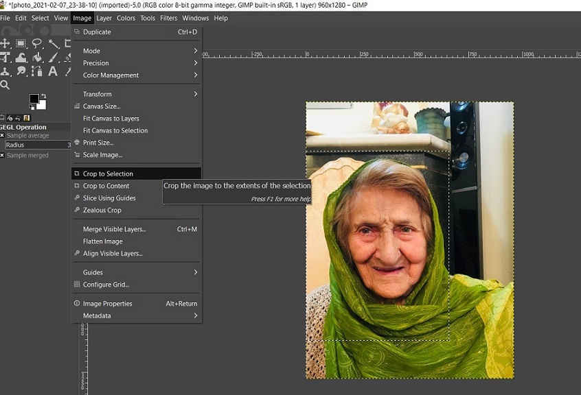
  • Figure 1. Changing saturation of the image.

  • Go to Colors>>Curves to the Curves function to deepen the shadows a bit.
  • Add a new layer on top of the image by clicking on Create a New Layer icon located in bottom right toolbar. Then, decrease Opacity of the created layer to around 15 percent.
  • Select Paintbrush tool and trace over outline of the subject.
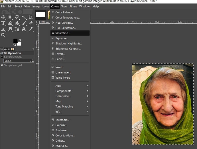
  • Figure 2. Tracing over outline of the image.

  • Make the size of the brush smaller and trace over the shadows.
  • Add another new layer and fill it with white color, then bring that down beneath the layer that we previously created. It helps to see the traces better.
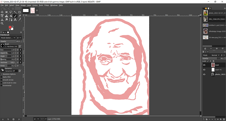
  • Figure 3. Adding a new layer with white color.

  • Turn off the visibility of the white layer and the original photo layer and increase the opacity to the maximum (100 percent).
  • Now, you should turn the red color to the black. Go to Colors>>Threshold and decrease the channel values.
  • Finally, Export the format you want and save the result.
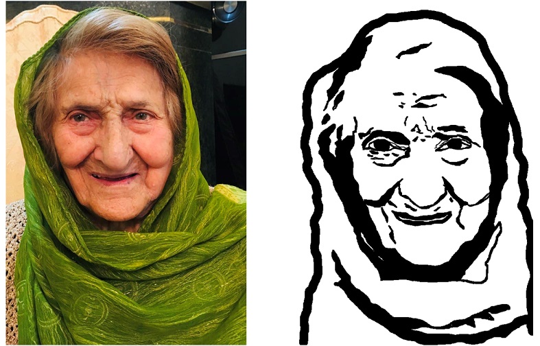
  • Figure 4. Original image vs proccessed image.

2D vector graphics

Because vector graphics are composed of true geometric primitives, they are best used to represent more structured images, like line art graphics with flat, uniform colors. Most created images (as opposed to natural images) meet these specifications, including logos, letterhead, and fonts. Common vector formats include AI, EPS, SVG, and sometimes PDF. Inkscape is a free and open-source vector graphics editor; it can be used to create or edit vector graphics such as illustrations, diagrams, line arts, charts, logos and complex paintings. Inkscape's primary vector graphics format is Scalable Vector Graphics (SVG); however, many other formats can be imported and exported.

For this week, I decided to design a kinf of logo for my further activites during Fab Academy. First, I downloaded the logos of Fab Academy and Fab Lab Oulu which is my local fablab. Then, I openned Inkspace and from File->Import..., I uploaded the first logo.

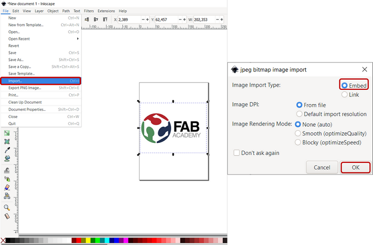
Figure 5. Importing a file in Inksapce

Then, from Path->Trace Bitmap..., you will see the three filter options available: Brightness Cutoff, Edge Detection and Color Quantization which I chose Brightness Cutoff . The "Brightness threshold" default was quite low and one part of the text was missing, so I had to increase it up to 0.890 to have the complete text with enough contrast. Then, press OK and you will see another layer created. I simply removed the original photo and kept the traced one for the rest.

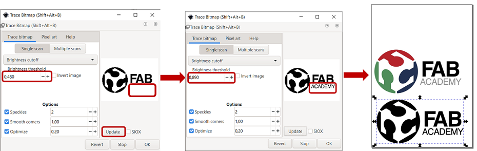
Figure 6. Setting Trace bitmap in Inkspace

Then, I added a text from the tool on the left side of the toolbar (Figure 7). Then, from the right side, you can edit the font type, size or style.

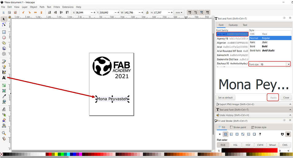
Figure 7. Setting Trace bitmap in Inkspace

To change both width and height by the same proportion, you can press the locker on the top toolbar (Figure 8)

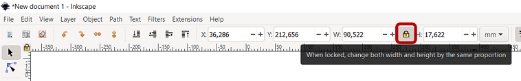
Figure 8. When locked, change both width and height by the same proportion

Then, I imported another logo for Fab Lab Oulu and did the same process for trace bitmap. But befor that, I tried to crop part of the logo which made me falimiar with a new feature in Inkspace. To crop an image in Inkspace, I drew a rectangular around the part I was going to keep. Then, I selected both objects (the full logo+rectangle) by pressing Shift and then, I clicked Object->Clip->Set which will remove the area out side of the rectangle.

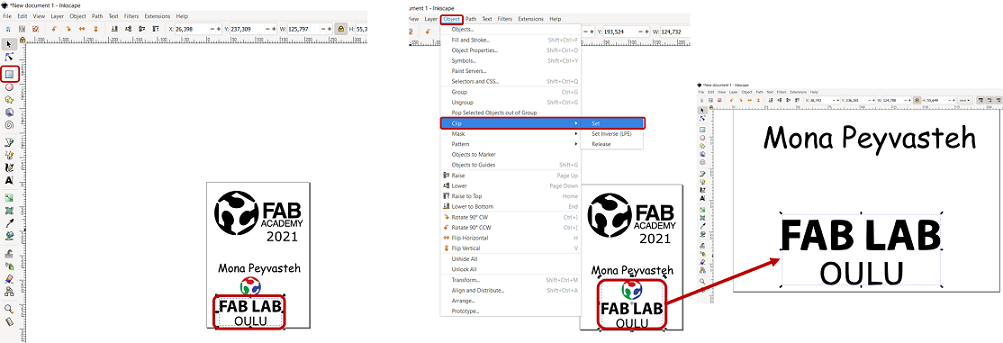
Figure 9. Crop process in Inkspace

Finally to make a frame, from the left bar, I drew an ellipse around the objects, then, to resize page to drawing, go to File->Document Properties->Resize page to drawing or selection.

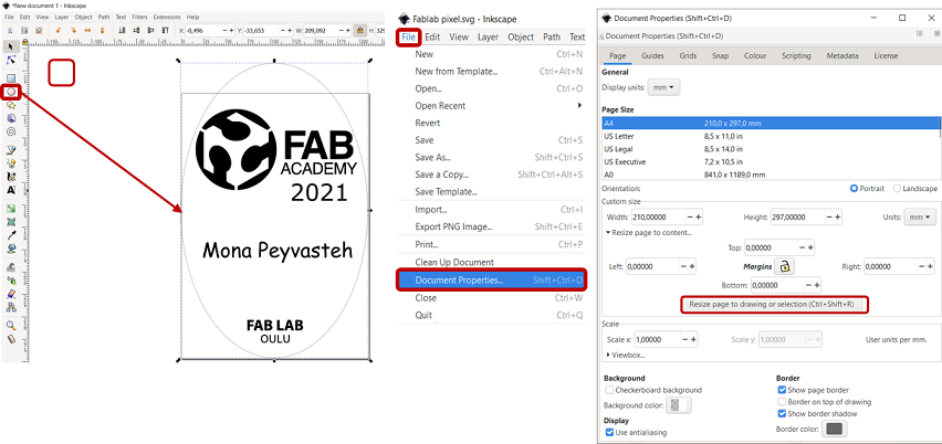
Figure 10. Making frame around drawing

Now, the file is ready!

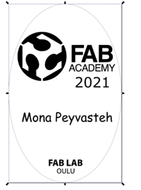
Figure 11. Final deign in Inkspace

3D Modelling

Blender

Blender is a free and open-source 3D computer graphics software toolset used for creating animated films, visual effects, art, 3D printed models, interactive 3D applications and video games. Blender's features include 3D modeling, UV unwrapping, texturing, raster graphics editing, rigging and skinning, fluid and smoke simulation, particle simulation, soft body simulation, sculpting, animating, match moving, rendering, motion graphics, video editing and compositing. Recently, I started to work with Blender to draw an image of the experimental setup I used in my work. I used several tutorials on YouTube and started to make a donut with Blender Guru ! After spending hours and hours struggling with lightning and shader features of Blender, I prepared a basic schematic image of the polarizers and meat samples as you see in Figure 12.

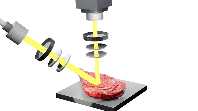
Figure 12. 3D Modelling Mueller imaging polarimetry measuring a meat sample with Blender.

Autodesk Fusion 360

To learn a new software and also, after discussing and exploring the pages of the former Fab Academy students, I decided to work with Autodesk Fusion 360 for 3D modelling part of the program. As the first step, I just watched some tutorials in YouTube ( example 1 and example 2 ) to get familiar with Fusion environment and learn some basic features.

Shortcuts in Fusion 360:

  • S=Model Toolbox
  • Q=Push/Pull
  • C=Circle
  • D=Dimension
  • L=Line
  • X=Construction
  • P=Project
  • Ctrl+Z=Undo
  • J=Joint
  • Since I have already an idea about my final project, I started with a simple sketch of the component I will need. To make a hexapod platform, I simply drew a sketch of the upper and lower planes and six legs of the hexapod. You can simply add and design different components and then, join or assemble them all together. For the upper plane, I draw a sketch through Sketch >> Circle >> Center diameter Circle.

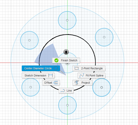
    Figure 13. Drawing sketches with Fusion 360.

    By clicking S (Model Toolbox), search for Center Rectangle and click the arrow to add it to Toolbox. To extrude the circles, Selecting Create >> Extrude or simply press E, click the surface and then dragging it up and setting the height you desired (Figure 14).

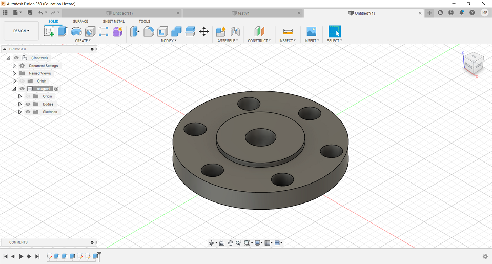
    Figure 14. Extruding with Fusion 360.

    Then, I added new components including the six legs and the lower plane. After that, I joined the components through Assemble button and finished the primary modelling of hexapod platform.

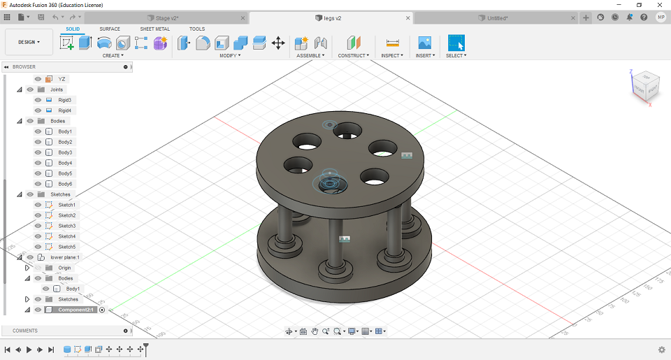
    Figure 15. Basic Hexapod drawing with Fusion 360.

    Files

    Reflection

    During this week, I learned about raster and vector concept in addition to learn some new features in GIMP. Then, I started to work with Fusion 360 for the first time that was a bit challenging in the beginnig but then, turned interesting. I also learned some new features using Inkspace.

    Mona Peyvasteh

    Fab Academy 2021

    Diary of my journey to the world of Digital Fabrication